

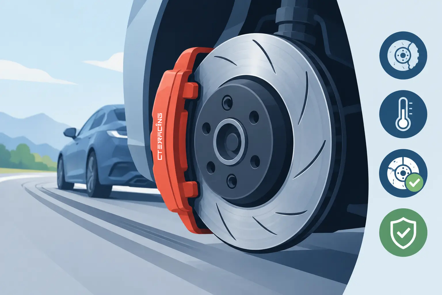
A cracked rotor is not a cosmetic problem. Under repeated high-speed braking, it can turn a confident brake pedal into vibration, noise, reduced consistency, and an immediate safety decision for the driver or workshop. To prevent rotor cracking, the brake system must manage heat as a complete assembly - not simply rely on a larger disc or a more aggressive pad.
For performance shops, distributors, and serious drivers, this distinction matters. Rotors crack when thermal energy, mechanical stress, installation error, or component mismatch exceeds the material's operating margin. The solution starts with proper hardware selection, then continues through installation, bedding, cooling, and disciplined inspection.
Why Brake Rotors Crack Under Load
Every braking event converts vehicle speed into heat. During a single hard stop, that heat enters the friction ring rapidly. During mountain driving, towing, track sessions, or repeated street pulls, the rotor may not have enough time to shed that energy before the next stop. The temperature gradient between the hot friction surface and cooler internal sections creates stress. Repeat the cycle often enough, and cracks can begin.
On iron rotors, cracks commonly develop near drilled holes, slots, vane transitions, or the outer edge of the friction face. Heat checking may first appear as fine surface lines. Some light surface checking can occur on heavily used track hardware, but a crack that grows across the friction face, reaches an edge, connects drilled holes, or changes the pedal feel is not normal wear. It requires inspection and, in many cases, replacement.
Carbon ceramic rotors operate differently from conventional cast iron discs. Their material structure offers major advantages in thermal resistance, corrosion resistance, and reduced unsprung weight, but they are not immune to damage. Incorrect pad compounds, impact damage, improper hardware, extreme thermal shock, or operation beyond the intended system design can compromise a carbon ceramic disc. A carbon ceramic system must always be treated as a matched, vehicle-specific brake package.
Prevent Rotor Cracking With Correct System Matching
The rotor, caliper, pad, bracket, brake lines, wheel clearance, and vehicle application must work together. Installing a high-friction race pad on a rotor that was not designed for its temperature range can concentrate heat at the disc surface. Fitting a large rotor without the correct caliper position can create uneven pad contact. Both conditions shorten service life regardless of how premium the individual components may be.
Pad selection deserves particular attention. A pad with excessive initial bite may feel impressive during a brief road test, yet it can produce unnecessary rotor stress when repeatedly loaded. Conversely, a pad compound that loses friction at temperature forces the driver to apply more pedal pressure and extend braking duration, loading the rotor even harder. The right compound depends on vehicle weight, tire grip, brake cooling, driving environment, and target temperature range.
For a Porsche, BMW, Nissan GT-R, Toyota Supra, Tesla, Defender, or supercar platform, fitment is more than bolt pattern and rotor diameter. Axle load, electronic brake control strategy, wheel design, and intended use all affect the right specification. A complete kit engineered for the platform gives the installer a controlled starting point. It also reduces the risk of mixing parts that look compatible but do not share the same thermal and mechanical requirements.
CCYS applies this system-level approach through vehicle-specific carbon ceramic brake solutions, supported by in-house engineering and production control across the critical manufacturing process.
Installation Errors That Create Rotor Stress
A rotor cannot run true on a contaminated or corroded mounting face. Even a small amount of rust scale, coating buildup, debris, or hub runout can introduce lateral runout. As the disc rotates, the pad contacts it unevenly. The result may be disc thickness variation, pedal pulsation, localized overheating, and a higher risk of crack development over time.
Before installation, clean the hub face carefully and measure runout with the correct tools. Confirm that the rotor seats fully, the center bore is correct, and the mounting hardware is specified for the application. Wheel bolts or lug nuts must be tightened in the prescribed sequence and to the vehicle manufacturer's torque specification. Uneven clamping force can distort the rotor hat and create a false diagnosis of warped rotors.
Avoid impact tools for final wheel tightening. They are fast, but they do not deliver consistent clamping load without verification. A calibrated torque wrench is a basic requirement for performance brake work. After the first heat cycle, recheck wheel torque when the vehicle manufacturer or kit instructions call for it.
Brake caliper alignment also matters. The pad should sweep the friction surface evenly, with no overhang that attacks the disc edge. Check caliper bolts, bracket fasteners, anti-rattle hardware, and pad retaining components. A loose or incorrectly positioned part can create localized contact that no rotor material can tolerate for long.
Bedding Is Heat Management, Not a Ritual
Improper bedding is one of the most avoidable reasons for uneven braking behavior and rotor distress. New rotors and pads need controlled heat cycles to establish a stable transfer layer between pad material and disc surface. Skipping this process can leave inconsistent deposits that feel like vibration, encourage hot spots, and make the driver mistake friction instability for rotor warping.
Bedding should follow the pad and brake-system manufacturer's procedure. In general, it involves a series of firm, progressive decelerations with enough cooling time to avoid holding the vehicle stationary with very hot pads clamped against the disc. Parking immediately after repeated hard stops can imprint pad material onto one area of the rotor. The next drive may reveal a pulse through the pedal, even when rotor thickness remains within specification.
The trade-off is straightforward: a track-oriented pad usually needs more temperature before it performs consistently, while a street-focused compound must remain stable during cold starts, traffic, and occasional hard use. Select the compound for how the vehicle is actually driven, not for the most aggressive description on the box.
Control Heat Before It Becomes a Crack
More rotor mass can absorb more energy, but capacity alone is not enough. The system must release heat between braking events. Proper internal vane design, directional rotor orientation, brake ducts, wheel airflow, and appropriate wheel clearance all contribute to cooling. Decorative wheel designs or poorly routed ducts can restrict airflow around the caliper and friction ring, trapping heat where it does the most damage.
Driving technique affects rotor life as well. On a track, a driver who drags the brakes for a long distance can generate more cumulative heat than a driver who brakes firmly and releases cleanly at the correct point. This does not mean every vehicle should use aggressive threshold braking on the street. Road conditions, tire grip, traffic, and vehicle balance always come first. It means the brakes should not be used as a constant heat source when a lower gear, greater following distance, or better line choice can reduce their workload.
After a demanding session, use a cooldown lap when conditions allow. Avoid stopping with the brakes applied immediately after maximum-temperature use. Let the system shed heat through airflow, then inspect it once it has cooled safely.
Inspect the Rotor Before the Damage Spreads
Routine inspection should be based on use, not only mileage. A daily-driven premium vehicle may need standard service interval checks. A track car, heavy EV, or modified SUV should be inspected after every event or after any braking episode that produced fade, smoke, vibration, unusual noise, or a burning odor.
Look closely at both friction faces, the outer edge, drilled holes or slot ends, rotor hats, and mounting points. Record rotor thickness and compare it with the minimum service specification. Check pad wear across the full surface. Tapered pads can indicate caliper movement, guide-pin problems, piston imbalance, or poor alignment that will continue to overload the rotor.
Do not judge a crack only by its visible length. Its location and direction matter. A superficial heat-checking pattern may be monitored according to the rotor manufacturer's guidance, while a radial crack that travels toward an edge or joins another crack is a replacement-level concern. For carbon ceramic discs, any suspected structural damage should be evaluated according to the system manufacturer's inspection criteria rather than treated like an iron rotor.
Build Brake Reliability Into the Entire Vehicle
Rotor durability depends on more than the braking kit. Worn control arms, ball joints, bushings, wheel hubs, or bearings can introduce vibration and instability that complicate brake diagnosis. Excessive wheel play can create runout. Soft or damaged suspension components can make braking loads less predictable, especially in a heavy performance SUV or high-speed road car.
This is why performance braking should be approached as a vehicle-control upgrade. The objective is not merely a larger disc behind the wheel. It is repeatable stopping force, stable pedal response, correct thermal behavior, and parts that remain dependable through real operating conditions.
When a customer reports vibration or visible cracking, resist the temptation to replace the rotor alone and send the car out. Verify pad compatibility, hub condition, caliper function, hardware torque, fluid condition, cooling path, and the driver's intended use. The best way to protect a racing-grade brake system is to diagnose the entire load path before the next hard stop demands more than the vehicle can safely deliver.