

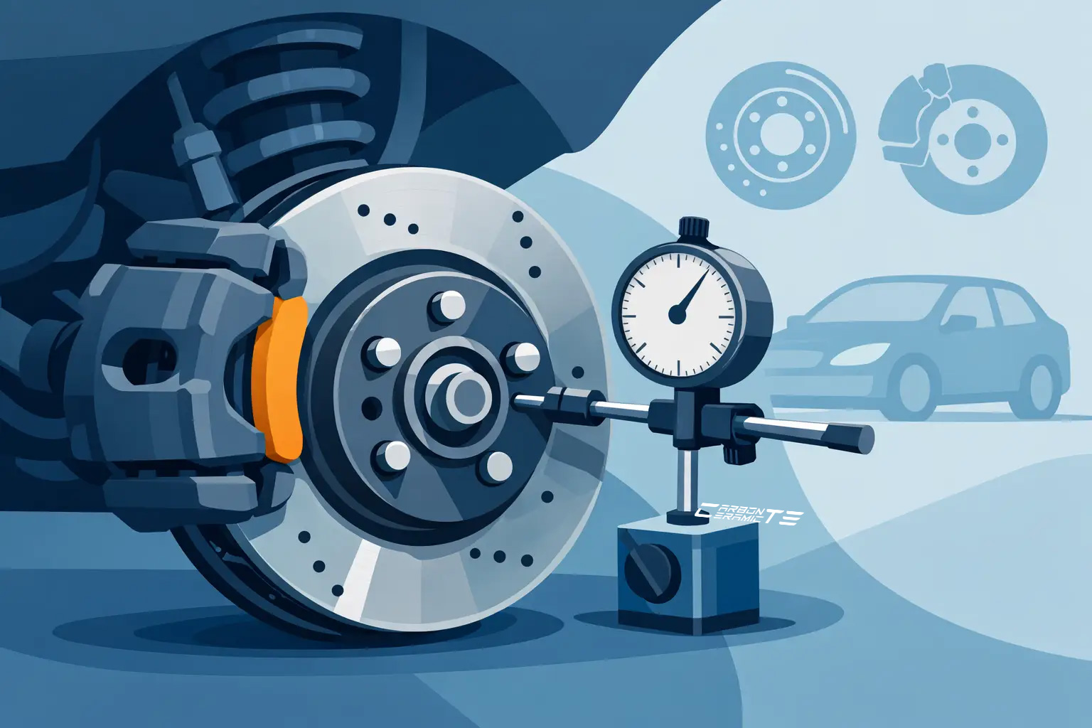
A brake pedal that pulses under pressure is more than an annoyance in a performance vehicle. It can undermine driver confidence at the end of a straight, mask an installation error, and accelerate uneven pad deposits. Before replacing expensive components, technicians need to measure brake disc runout correctly and identify whether the source is the disc, hub, mounting face, or installation process.
On a high-performance braking system, precision at the mounting interface matters as much as friction material or caliper clamping force. A rotor that does not run true pushes the pads apart once per revolution. That movement can create pedal feedback, inconsistent pad contact, and, over time, disc thickness variation that feels like a warped rotor even when the original problem began elsewhere.
What Brake Disc Runout Actually Means
Brake disc runout is the side-to-side movement of the disc as it rotates around the hub. It is measured at the friction surface with a dial indicator and normally expressed in thousandths of an inch or millimeters. It is not the same as disc thickness variation, which is a change in thickness around the disc circumference.
The distinction matters. Excessive lateral runout can contribute to thickness variation over mileage because the pads repeatedly contact the disc unevenly. But a vibration complaint can also come from uneven friction deposits, a damaged hub, loose wheel bearings, suspension play, or incorrect wheel installation. Measuring is how a workshop stops guessing.
There is no single acceptable runout figure for every vehicle or brake package. Always use the vehicle manufacturer's service specification and the brake system supplier's installation requirements. Performance applications may have tighter tolerances than standard street vehicles, while two-piece or floating-disc designs require an understanding of their intended movement and mounting design.
Tools Needed to Measure Brake Disc Runout
A dial indicator with a stable magnetic base is the essential tool. The indicator should have sufficient resolution to show small movements clearly. A clean wire brush or non-marring abrasive pad, brake cleaner, torque wrench, wheel nut or bolt hardware, and the vehicle's service data are equally necessary.
Do not measure a disc that is loosely sitting on the hub. With the wheel removed, secure the disc using the correct wheel hardware and suitable washers or spacers where needed. Tighten it in a star pattern to the specified wheel torque. This duplicates the clamping force that centers the disc during normal operation. Measuring an unsecured rotor often produces meaningless readings.
For vehicles using wheel bolts, use appropriate temporary hardware that provides full thread engagement. Never improvise with damaged studs, mismatched threads, or excessive torque. The purpose is accurate measurement, not simply holding the disc in place.
How to Measure Brake Disc Runout Step by Step
Prepare the hub and disc mounting faces
Raise and support the vehicle safely, remove the wheel, and inspect the disc, hub flange, and center bore. Rust scale, paint overspray, trapped debris, corrosion around the pilot, and burrs on the mounting face can create measurable runout immediately.
Clean the hub face thoroughly without removing base material. The surface must be flat, dry, and free of raised corrosion. Clean the mating face and center bore of the disc as well. On premium brake systems, a small particle trapped between these surfaces can create a large enough error to affect pedal feel.
Inspect the hub pilot for damage and confirm the disc seats fully. If a disc appears difficult to install or rocks on the hub, stop and correct the fitment issue before proceeding. Forcing a component into place can damage the center bore or conceal the real cause of the problem.
Secure the disc at operating clamp load
Install the disc and use at least three evenly spaced wheel fasteners, or the number required by the service procedure. Tighten them gradually in a star pattern to the specified torque. Do not use an impact wrench for the final tightening step.
This step is especially critical on high-performance hubs, where uneven clamping can distort the measurement. If the disc is retained by a set screw, remember that the screw locates the disc during assembly but does not replace wheel clamping force.
Position the dial indicator
Mount the magnetic base to a rigid, non-rotating component such as the knuckle or suspension structure. Avoid thin dust shields or any surface that can flex. Position the indicator tip perpendicular to the disc friction face, generally near the outer portion of the swept area but away from holes, slots, edges, and obvious wear marks.
Preload the indicator slightly, then zero the gauge. Rotate the disc slowly through one complete revolution while watching the needle. Do not spin it quickly. A slow, controlled rotation makes it easier to identify the highest and lowest readings and prevents a loose bearing or indicator stand from creating false results.
Record the total indicator movement from the lowest point to the highest point. That total is the lateral runout. Repeat the check once to confirm the reading rather than relying on a single pass.
Check hub runout when disc runout is high
If brake disc runout exceeds the applicable specification, remove the disc and measure the hub flange itself. Position the indicator on the hub mounting face at a similar radius, then rotate the hub carefully. Any excessive hub runout will transfer directly to the installed disc.
Also check for wheel-bearing play before condemning the hub. Movement at the bearing can change the reading as the hub is rotated. A worn bearing, damaged flange, or debris behind the hub can turn a new disc installation into a repeat comeback.
How to Isolate the Cause of Excessive Runout
If hub runout is within specification but the installed disc is not, mark the relationship between the disc and hub, then index the disc to a different wheel-stud or bolt-hole position. Reinstall it at the correct torque and measure again. Indexing can reveal whether the high point of the disc is combining with a high point on the hub.
A substantial improvement after indexing points to tolerance stack-up between otherwise serviceable parts. If the reading stays high in every position, inspect the disc for damage, incorrect machining, a distorted hat section, or improper application. Confirm that the part number, center bore, offset, and mounting design match the vehicle exactly.
For a two-piece floating disc, inspect the hat, fasteners, bobbins, and directional orientation according to the supplier's instructions. Some axial movement at the friction ring may be designed into a floating system, but that does not eliminate the need for correct mounting-face runout. Measure where the manufacturer specifies and do not treat intentional float as a defect.
Carbon ceramic discs require even more discipline. Their performance advantages include reduced unsprung weight and exceptional thermal resistance, but they are not parts to machine, resurface, or handle casually after an installation error. If a carbon ceramic disc shows abnormal runout, follow the system manufacturer's inspection procedure and replace components when required. Do not attempt conventional rotor correction methods on a component that is not designed for them.
Installation Practices That Prevent Repeat Problems
Runout control starts before the dial indicator comes out. Technicians should keep friction surfaces free from oil and fingerprints, avoid striking the disc during installation, and torque wheels only with calibrated equipment. Wheel hardware must be correct for the seat type, thread engagement, and vehicle specification.
After the first road test, assess pedal feel under controlled braking and follow the pad bedding procedure supplied with the brake kit. A proper bedding cycle establishes a stable transfer layer. It cannot correct excessive runout, but it helps prevent a separate source of judder that is often misdiagnosed as a bent disc.
On vehicles exposed to track temperatures, aggressive street use, or heavy loads, inspect the wheel hub, bearings, caliper mounting hardware, and suspension joints as part of the same service decision. Brake performance is a system result. A precision disc cannot compensate for a hub face compromised by corrosion or a chassis component with excessive play.
CCYS engineers complete carbon ceramic brake systems around vehicle-specific fitment, controlled manufacturing, and racing-grade thermal performance. That level of braking capability deserves the same precision during installation and inspection.
When the dial indicator shows a clean, repeatable result within specification, the technician has more than a number. They have evidence that the disc, hub, and mounting process are ready to support consistent pedal feel when braking demand becomes serious.