

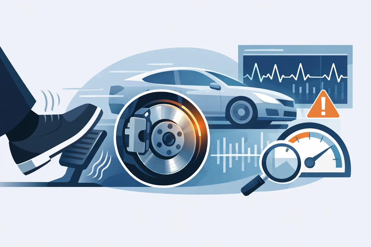
A brake pedal that pulses under your foot is not a cosmetic issue. At highway speed, under repeated hard braking, or during a late braking zone, vibration can reduce driver confidence exactly when the vehicle needs predictable stopping control. Diagnosing brake pedal vibration correctly means separating a true brake-disc problem from wheel, hub, caliper, bearing, or chassis faults before expensive parts are replaced unnecessarily.
For performance workshops and serious vehicle owners, the first rule is simple: do not diagnose by appearance alone. A disc can look clean and still have excessive lateral runout, thickness variation, or uneven friction transfer. Conversely, a visible heat mark does not automatically mean the disc is permanently damaged. Measure first, then repair the cause.
What Brake Pedal Vibration Usually Tells You
Brake pedal pulsation occurs when brake torque changes as the rotor turns. The driver feels that changing torque through the hydraulic system and pedal. If the steering wheel also shakes, the condition is often more pronounced at the front axle, but that is not a complete diagnosis. Rear brake vibration can still travel through the chassis and be felt at the pedal, seat, or cabin floor.
The speed and conditions of the vibration matter. A pulse that appears only during light braking from 70 mph may point toward disc thickness variation or friction deposits. A severe shake during heavy braking can involve rotor runout, loose suspension components, wheel-bearing movement, or a brake system that has been repeatedly overheated. A vibration present even when the brakes are not applied is more likely related to tires, wheels, hubs, driveline components, or chassis hardware.
For high-performance cars, the operating history is equally valuable. Track use, mountain driving, towing, repeated autobahn-style deceleration, improper bedding, long periods of storage, and recent wheel or brake work can all change the direction of the inspection.
Diagnosing Brake Pedal Vibration Step by Step
Confirm the Driver’s Complaint
Start with a controlled road test where conditions allow. Record vehicle speed, brake pressure, steering-wheel response, pedal behavior, noise, and whether the vehicle pulls left or right. A vibration at one exact speed range may indicate wheel imbalance or a resonance issue rather than a brake fault. A repeatable pulse that rises and falls directly with wheel speed during braking is much more likely to originate at the disc, hub, or brake assembly.
Do not overlook the difference between pedal pulsation and ABS activation. ABS creates a rapid, mechanical pulsing sensation when the control system detects wheel lock. If ABS intervention occurs during ordinary dry-road braking, inspect wheel-speed sensor data, tone rings, wiring, tire circumference differences, and bearing play before condemning brake discs.
Inspect the Friction Surfaces and Hardware
With the wheels removed, inspect both rotor faces, pads, calipers, brake hoses, mounting hardware, and dust shields. Look for cracking, deep scoring, heat checking, blue or dark hot spots, uneven pad contact, tapered pad wear, seized slide hardware, damaged caliper boots, and contact between the shield and rotor.
Uneven pad deposits deserve special attention. What drivers often call a “warped rotor” is frequently disc thickness variation caused by uneven friction material transfer. This can develop after the vehicle is held stationary with hot pads clamped against hot discs, after incorrect bedding, or when pad material and rotor surface condition are poorly matched. The resulting high-friction areas create changing brake torque and pedal pulsation.
On carbon ceramic systems, inspection standards should be even more disciplined. Carbon ceramic discs operate differently from cast iron and should not be judged by iron-rotor assumptions. Surface appearance, wear measurement, pad compatibility, bedding history, and manufacturer service limits all matter. Unapproved machining, aggressive abrasives, or incompatible pads can compromise a high-value braking system.
Measure Rotor Runout and Thickness Variation
A dial indicator is the correct tool for checking lateral runout. Mount it securely, position the indicator on the rotor friction face, and rotate the disc slowly. Compare the reading with the vehicle and brake manufacturer’s specification. Excessive runout can push the pads and pistons back as the rotor rotates, creating pedal movement on the next brake application.
Then measure rotor thickness at multiple points around the disc, at a consistent distance from the outer edge. A micrometer is preferred. Thickness variation may be small enough to escape visual inspection yet large enough to create a noticeable pedal pulse at road speed.
If runout is excessive, do not immediately replace the rotor. Remove it and measure the hub face. Corrosion, scale, paint, dirt, burrs, or trapped debris between the hub and disc can create runout even with a new, correctly manufactured rotor. Check the wheel mounting face as well. A distorted wheel, incorrect wheel seating, or uneven wheel-bolt torque can contribute to the problem.
Check the Hub, Bearing, and Wheel Installation
Hub condition is one of the most commonly missed causes of recurring vibration. A new rotor installed on a contaminated or damaged hub face will inherit that error. Clean the mounting surface carefully, remove corrosion without gouging the metal, and verify that the disc seats fully and flat.
Check wheel bearing play and hub runout. A bearing that allows movement under load can alter rotor position during braking and create inconsistent pad contact. On performance vehicles with large brake packages, high-grip tires, and repeated heat cycles, small amounts of movement that might go unnoticed in normal commuting can become obvious under heavy deceleration.
Wheel bolts or lug nuts must be tightened in the correct sequence and to the specified torque. Impact-gun installation without final torque verification is not acceptable for a precision brake assembly. Uneven clamping load can distort a rotor hat or wheel interface enough to create a vibration complaint.
Do Not Ignore Calipers and Chassis Components
A rotor is only one part of the system. A sticking caliper piston, seized guide pin, restricted brake hose, or weak pad-retaining hardware can cause uneven pad pressure and localized heat. The evidence may include one pad worn more heavily than the other, a vehicle pull, excessive rotor temperature on one corner, or a hot-brake odor after normal driving.
Chassis wear can amplify a brake vibration into a steering shake. Inspect control arms, ball joints, tie-rod ends, rack ends, stabilizer links, bushings, and wheel bearings for play. Under braking, worn components allow the wheel to move fore and aft or change toe angle. The brake system may be functioning correctly, but the chassis can no longer hold the tire contact patch stable.
This distinction matters for workshops. Replacing discs without correcting a loose control arm bushing or worn ball joint can produce a short-lived improvement, followed by a customer return and an avoidable warranty dispute.
Match the Repair to the Root Cause
Once measurements identify the fault, repair the entire condition rather than the most visible component. Rotor replacement may be required when thickness is below the service limit, cracking is present, disc thickness variation cannot be corrected within specification, or thermal damage is confirmed. But a rotor replacement should also include hub preparation, correct pad selection, caliper inspection, proper hardware service, and torque-controlled wheel installation.
When upgrading a vehicle used for repeated hard braking, component matching is critical. Larger discs, monobloc calipers, properly formulated pads, high-quality brake fluid, and vehicle-specific mounting hardware must work as a system. A racing-grade brake package cannot deliver consistent results if installed over worn hubs, compromised bearings, or unstable suspension joints.
CCYS applies this systems approach to carbon ceramic brake solutions and supporting chassis components, with manufacturing control across R&D, machining, and quality management. For distributors and workshops, the practical advantage is clear: fitment-specific parts and technical consistency reduce the risk of solving one braking problem while creating another.
Preventing Vibration After the Repair
The final road test should confirm a firm, stable pedal through a range of deceleration levels. Follow the pad and disc manufacturer’s bedding procedure, especially after installing performance pads or carbon ceramic components. Avoid holding the vehicle at a standstill with heavy pedal pressure immediately after repeated high-energy stops when conditions permit. Let the system cool through normal airflow instead.
Treat brake pedal vibration as a measurement problem, not a guesswork problem. The repair that lasts is the one built on verified runout, disc condition, hub integrity, caliper function, wheel torque, and chassis stability. When every component is working to specification, the driver feels what a performance brake system is supposed to deliver: controlled, repeatable stopping force when the pressure is highest.