

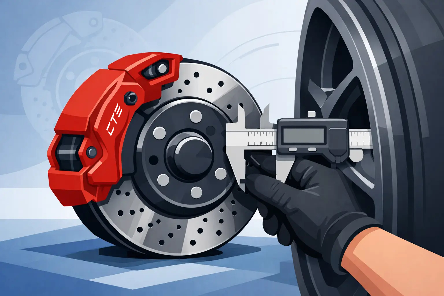
A brake kit can clear the wheel barrel on the shop floor and still contact a wheel spoke under load. That is the expensive, safety-critical mistake that accurate caliper clearance measurement is designed to prevent. Before installing larger carbon ceramic rotors, monobloc calipers, or a complete big brake kit, the wheel and brake assembly must be evaluated as one engineered system.
For performance workshops, distributors, and vehicle owners, this is not a cosmetic fitment check. Insufficient clearance can damage caliper paint and wheel finish, create noise, restrict wheel rotation, compromise component life, and, in a severe case, make the vehicle unsafe to drive. A proper measurement process confirms that the brake package has room where it needs it: around the caliper body, across the wheel barrel, at the spokes, and through the full operating range of the suspension.
What Caliper Clearance Measurement Actually Checks
Caliper clearance measurement is the process of verifying the available space between a wheel and the brake caliper, rotor, mounting hardware, and related components. Most fitment failures occur because people reduce this task to one question: “Will the wheel fit over the brakes?” The better question is whether the wheel will maintain safe clearance in every critical direction.
The first is radial clearance. This is the space between the outermost portion of the brake system, usually the caliper bridge or rotor assembly, and the inside diameter of the wheel barrel. A wheel may have the correct nominal diameter, such as 19 or 20 inches, but still have a barrel profile that conflicts with a large caliper or oversized rotor.
The second is axial clearance, often called spoke clearance. This is the distance from the caliper’s outer face to the back of the wheel spokes. It is frequently the deciding factor with modern concave wheels, factory wheels with thick spoke sections, and wheels designed around compact OE brake hardware. Wheel offset alone does not confirm axial clearance because spoke shape can change dramatically from the hub outward.
The third is clearance at the wheel mounting face and hardware. Hub centric rings, wheel weights, valve hardware, rotor hats, banjo fittings, brake lines, and caliper bolts can all affect usable space. A wheel that appears to clear by a narrow margin may still contact an adhesive balancing weight placed inside the barrel.
Why Wheel Diameter and Offset Are Not Enough
A 20-inch wheel is not automatically a 20-inch wheel from a brake-fitment perspective. Manufacturers use different barrel drops, spoke curvature, casting thicknesses, forging profiles, and mounting-pad designs. Two wheels with the same diameter, width, and offset can have very different internal geometry.
Offset is still essential because it sets the wheel’s position relative to the hub. However, it cannot describe the three-dimensional shape behind the spokes. This is why a wheel with a more aggressive concave face may clear a large caliper better than a flatter design with identical published dimensions. It depends on where the spokes begin their inward curve and how much material is present near the caliper’s widest point.
Brake hardware also varies. A six-piston monobloc caliper, for example, may be physically more compact and more rigid than a multi-piece alternative, yet its clearance envelope will depend on piston arrangement, bridge design, pad retention method, rotor diameter, and mounting bracket. Carbon ceramic systems reduce unsprung weight and manage repeated high temperatures effectively, but the wheel-fitment process remains just as exacting as it is with iron-disc systems.
How to Measure Caliper Clearance Before Installation
The most reliable method is to use a vehicle-specific brake template supplied for the exact caliper and rotor configuration. A template represents the brake system’s required clearance envelope at the hub mounting plane. It gives a workshop or wheel supplier a repeatable way to compare the proposed wheel against the brake kit before parts are installed.
Print the template at 100% scale on rigid material or mount it to cardboard, then verify its reference dimension with a caliper or steel rule before using it. Printer settings can quietly alter scale, especially when “fit to page” is selected. A template that is only slightly undersized can approve a wheel that does not actually fit.
Mount the template flat against the wheel mounting face, replicating its position on the hub. Then inspect the available room through the wheel barrel and behind each spoke. Rotate the template around the wheel because spoke geometry is not always perfectly uniform, particularly on directional, asymmetrical, or multi-piece designs.
If a physical template is unavailable, a dimensional drawing or a 3D wheel-and-brake scan can provide useful information. However, a wheel overlay from a manufacturer’s catalog should be treated as a preliminary screen rather than final approval unless both datasets use verified reference points and tolerances. For a high-value brake upgrade, physical confirmation remains the safer standard.
Measure the Wheel, Not Just the Wheel Model
Wheel-model fitment databases can be helpful, but they do not replace inspecting the actual wheel. Production revisions, different offsets, center-disc options, wheel repairs, powder coating, and prior machining can change the result. Used wheels deserve particular attention because a previous impact or repair may affect runout and internal profile.
Also check the intended tire and wheel package. Wider wheels and different offsets can alter suspension, fender, and steering clearance even when caliper-to-wheel space is adequate. On front steering axles, turn the wheels from lock to lock and inspect the full system rather than approving brake clearance in a straight-ahead position only.
Allow for Real-World Movement and Tolerance
A static test with the car on a lift is only the start. Wheels flex under cornering load, tires deflect, hubs have manufacturing tolerances, and brake components expand as temperatures rise. A racing-grade brake system must not rely on a near-zero gap that disappears during hard use.
There is no single universal clearance number that applies to every vehicle, wheel construction, and intended use. A forged wheel used for street driving and a cast wheel subjected to track curbing do not behave identically. The correct target is the brake kit manufacturer’s documented minimum clearance, supplemented by a sensible margin for wheel movement, balancing weights, and installation variation.
Avoid solving a tight fit with an arbitrary spacer. A spacer can create room at the spokes, but it also changes effective offset, bearing load, scrub radius, fender clearance, and stud or bolt engagement. On hub-centric applications, the spacer must preserve proper centering and use correctly engineered fastening hardware. A spacer is a fitment component, not a shortcut for an unverified installation.
Common Causes of Caliper-to-Wheel Interference
Several problems appear repeatedly in brake upgrades. The most common is assuming that a larger wheel diameter guarantees clearance. The next is trusting offset specifications without checking the spoke profile. Both approaches can lead to interference at the caliper’s outer corners, where clearance is often tightest.
Other recurring causes include:
- Adhesive wheel weights placed in the caliper sweep area
- Incorrect rotor hats, brackets, or left-right component placement
- Wheel spacers that reduce thread engagement or eliminate hub-centric support
- Bent wheels, excessive runout, or damaged bearings
- Calipers that are not correctly centered over the rotor after installation
The last point matters more than many installers expect. If rotor centering is wrong, pad wear can become uneven and the caliper may sit closer to one side of the wheel than the brake design intends. Verify bracket orientation, mounting surfaces, torque values, rotor-hat seating, and all supplied hardware before judging final clearance.
A Professional Fitment Verification Process
A disciplined inspection begins before ordering. Confirm the vehicle year, model, trim, drivetrain, axle, OE wheel diameter, and proposed aftermarket wheel specifications. Performance platforms can have substantial differences within the same model family, including axle loads, hub dimensions, electronic parking-brake configurations, and factory rotor sizes.
Next, compare the exact brake-kit template with the actual wheel. Do not substitute a template from a similar-looking caliper or assume a rear kit will clear because the front kit does. After installation, rotate the wheel by hand, inspect clearance through a complete revolution, and confirm that no wheel weight, spoke, or barrel section approaches the brake hardware too closely.
Then complete a controlled road test. Listen for contact during low-speed steering input, over suspension transitions, and under initial brake applications. After the brake system has reached operating temperature, reinspect the wheel interior and caliper for witness marks. If there is any sign of rubbing, remove the wheel and correct the root cause before returning the vehicle to service.
For distributors and workshops building repeat business, recording approved wheel part numbers, offsets, tire sizes, and brake configurations creates valuable fitment intelligence. It reduces installation time on future vehicles and gives customers a more confident recommendation than a generic statement that a wheel “should fit.”
Fitment Accuracy Supports Brake Performance
A high-performance brake system is engineered to deliver repeatable stopping force, thermal resistance, pedal confidence, and durability under demanding use. That engineering value is lost when fitment is treated as an afterthought. Correct clearance protects the wheel and caliper, but it also preserves the system’s intended alignment, cooling path, and serviceability.
CCYS applies the same discipline to brake-system development, with 90% of manufacturing controlled in-house and quality processes aligned with IATF 16949 and ISO 9001 standards. For a complete carbon ceramic brake upgrade, vehicle-specific engineering and a confirmed wheel interface are as important as the rotor material or piston count.
The right final decision is not based on how close the wheel can sit to the caliper. It is based on verified, repeatable clearance that lets the driver apply the brakes hard, lap after lap or mile after mile, without wondering what is happening behind the spokes.